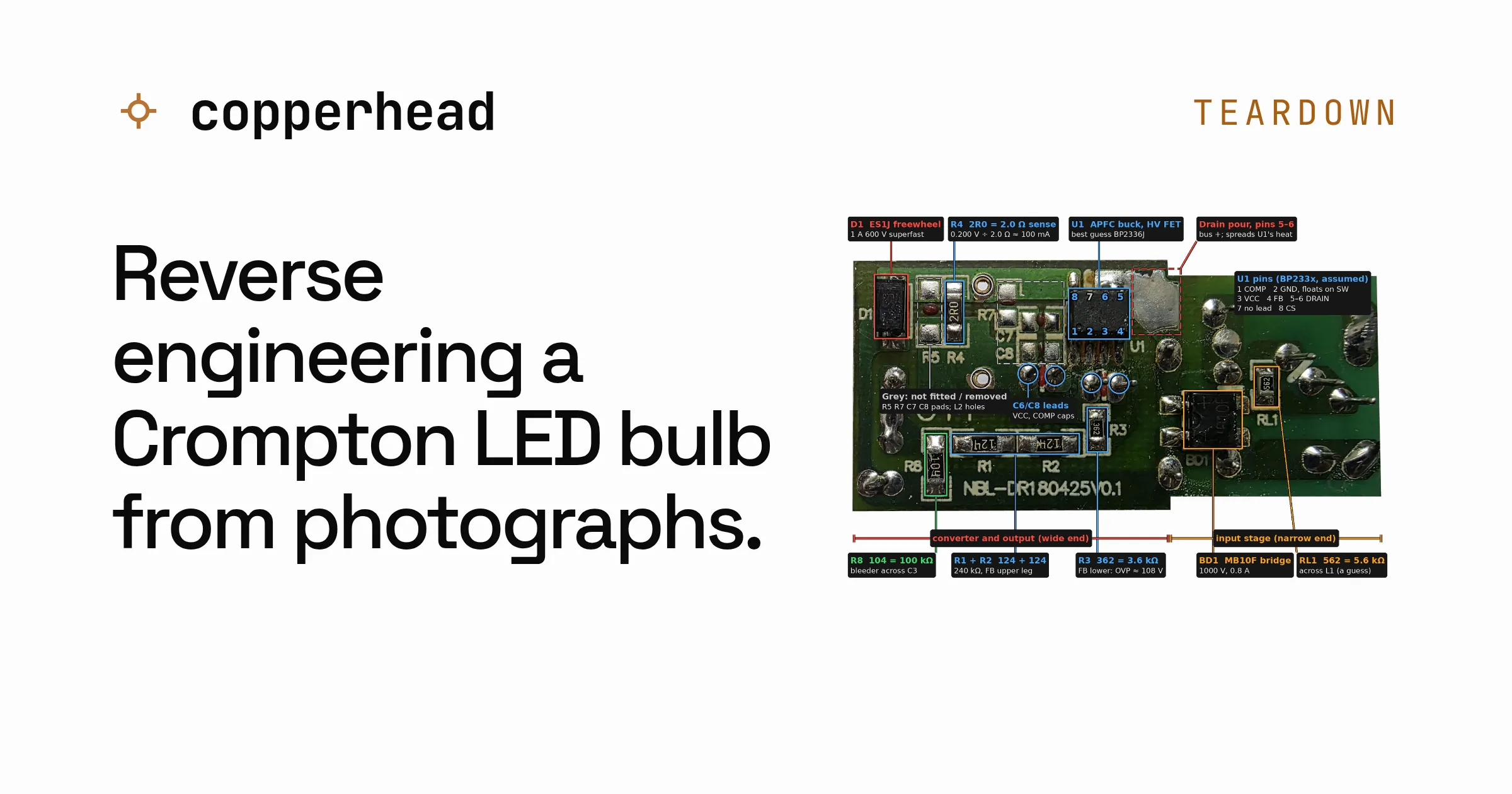

My Crompton LED bulb went dim and started to flicker. I replaced it, then reverse engineered the old one from 54 phone photos with copperhead. It found an LED board driven past its own label, a burn mark on one of the LEDs and a controller chip it could only name as a best guess.
The bulb went dim first. A little later it started to flicker. I put in a new one and was left holding the old one, a Crompton 9 W with a date code of February 2019, not sure what to do with it. Throwing it out felt like a waste, so I opened it instead.
Part of the fun of taking a product apart is that you might not get it back together. This one had already been replaced and was headed for the bin, so the worst case was that it went there in more pieces.
I decided to work from photos alone with no multimeter and without powering it up again. I pulled it apart and shot both sides of each board with my phone. That came to 54 photos, most of them in ten minutes and the rest a few hours later with a ruler in the frame.
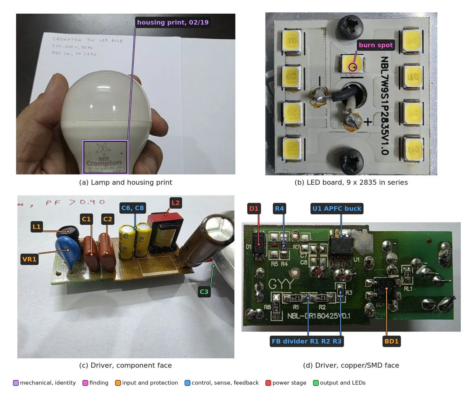
What came out of the bulb: the housing, the LED board and both sides of the driver board that sits in the neck.
Running copperhead backwards
copperhead usually goes from a written brief to a circuit board. Its reverse engineering framework runs the other way, from photos to the circuit, the parts, the risks and a record of how sure it is about every claim.
In that record anything read straight off a photo is marked observed. Anything calculated from those readings is derived, with the working next to it. A judgement call is inferred and gets a confidence between 0 and 1. When two pieces of evidence disagree it records both and flags the conflict. It also keeps a list of the 19 things it doesn’t know about this bulb and marks up the photos with the continuity checks that would answer them.
It went looking online too. As far as it could find, nobody has written up the inside of a Crompton bulb. The only outside evidence was repair videos[1][2][3]. YouTube wouldn’t let it download them, so it read what it could from thumbnails, the first minute of one video and storyboard frames 160 pixels wide.
Taking it apart
The diffuser dome comes off the housing. Under it is an aluminium cup, and the LED board sits on that cup on a layer of thermal grease, held by two self-tapping screws. That board is the part people swap in bulb repair videos, which takes those two screws and two wires. The driver board hangs on its wires inside the neck with no mounting holes at all.
The plastic rim cracked while I was prying it open and the big inductor came off the driver board on the way out. Both would have mattered more if I were putting it back together.
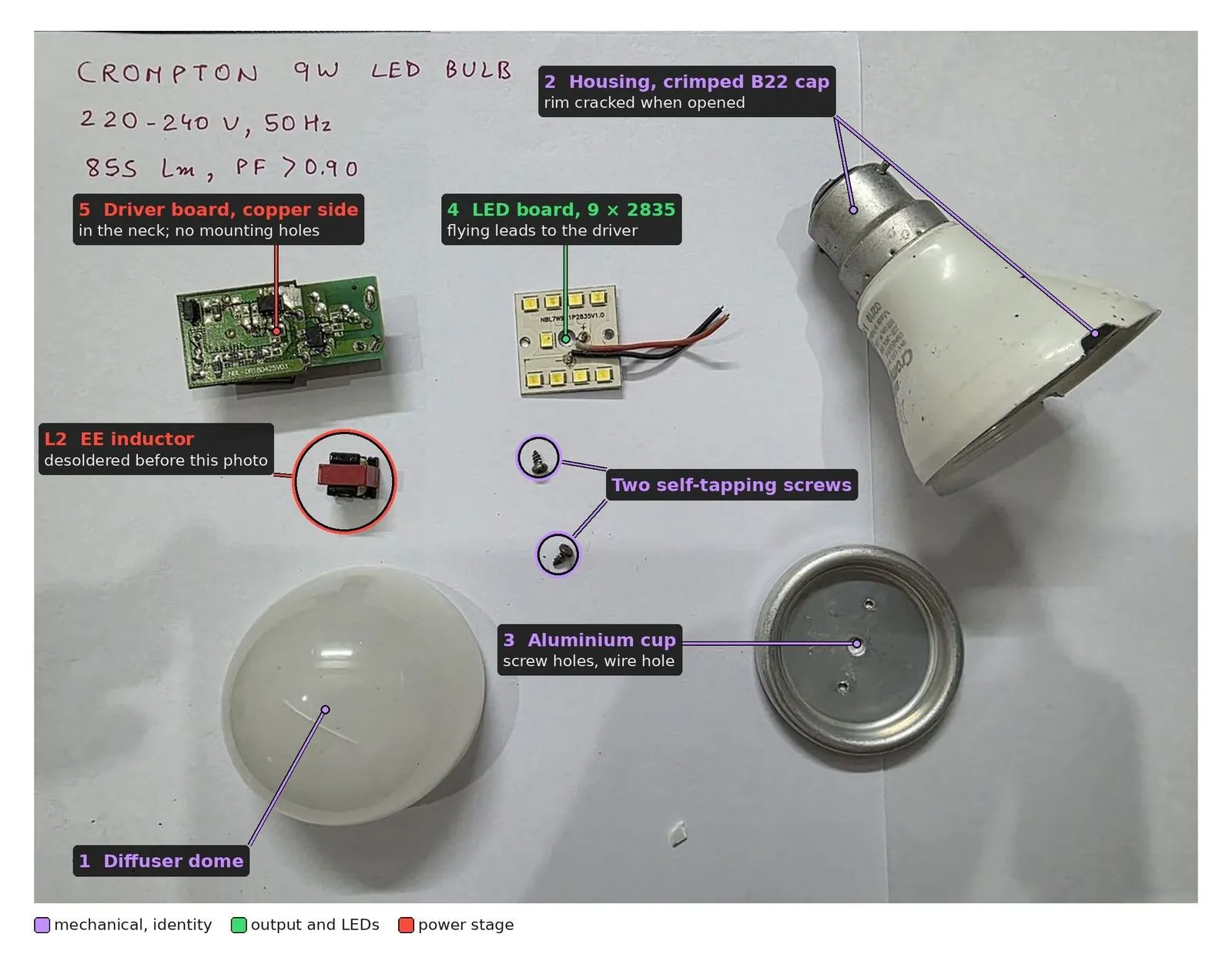
Everything that came out, numbered from the outside in. The handwritten note is my copy of what’s printed on the housing.
A driver with no big capacitor on the mains side
The driver is about 48 by 24 mm with roughly 20 parts on one copper layer. The bigger through-hole parts sit on one face and the small surface-mount parts are glued to the copper face, so the board gets soldered in a single pass over a solder wave. Red glue dots also mark a few empty footprints: spare positions for alternative parts and one for trimming the LED current.
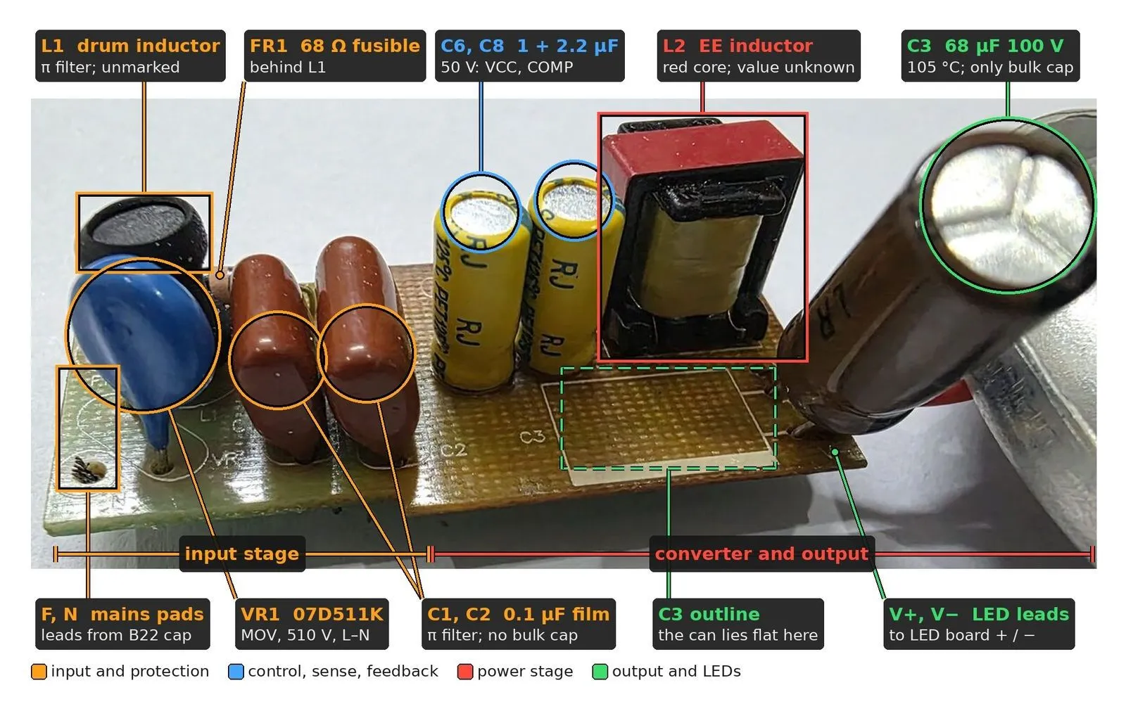
The through-hole face. Mains comes in on the left and the converter and the output capacitor take up the right.
Mains comes in through a 68 Ω fusible resistor, which does the job of both a fuse and an inrush limiter. Next is a 510 V varistor across the line to catch spikes, an MB10F bridge rectifier[4] and a small π filter made of two 0.1 µF film capacitors around a drum inductor. There is no big electrolytic capacitor on the mains side and no X or Y capacitors.
Without one, the controller chip runs straight off the rectified mains and shapes the current it draws to follow the sine wave, which is how the bulb gets the power factor above 0.9 printed on its housing. It works because the LED string is low voltage. The chip is a buck converter, so it can draw power only while the mains is above the LED voltage, about 81 V here against a 325 V peak. It goes quiet for about 14 degrees either side of each zero crossing. The lamp’s big capacitor, 68 µF at 100 V, sits across the LEDs instead and smooths what reaches them.
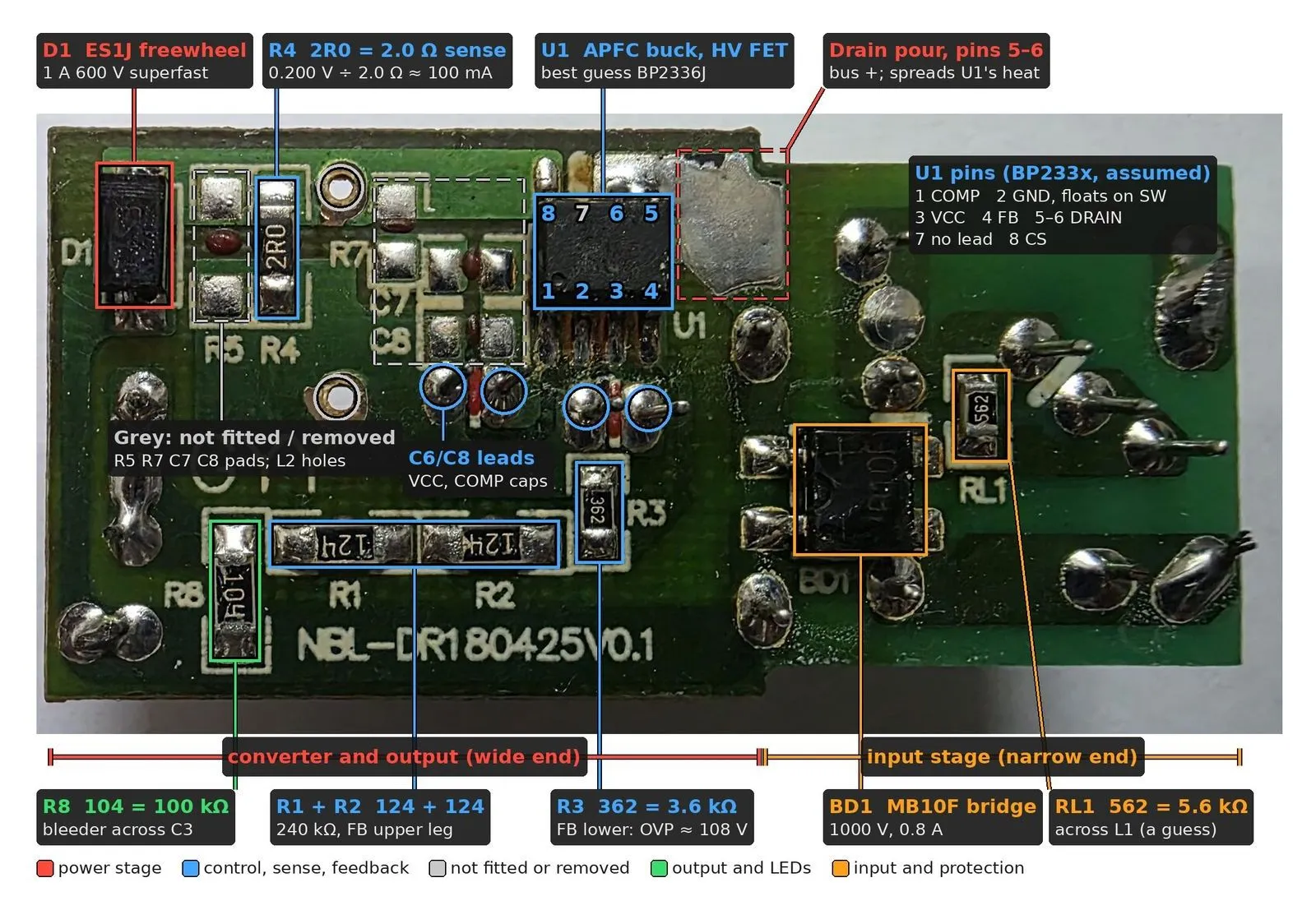
The copper face, where the controller lives. The pin map comes from the datasheet of the best-guess chip, and the grey boxes are empty footprints.
On this side the chip’s supply and loop capacitors are placed right at its pins, and its drain pins sit on a big copper pour that spreads the heat. The top half of the feedback divider is two 120 kΩ resistors in series where you’d expect one 240 kΩ. That looks odd until you work out that it sees about 244 V on every switching cycle, more than the 200 V a single resistor of that size is rated for.
Part markings and date codes
Resistors and capacitors carry short codes, and once the photo is sharp enough the
decoding is mechanical. 2R0 is 2.0 Ω. 124 is 12 followed by four zeros, so 120 kΩ.
07D511K is a 7 mm disc rated 510 V[5]. The fusible
resistor uses five colour bands instead. Blue, grey, black and gold read as 68 Ω at 5%.
Nobody decoded the fifth.
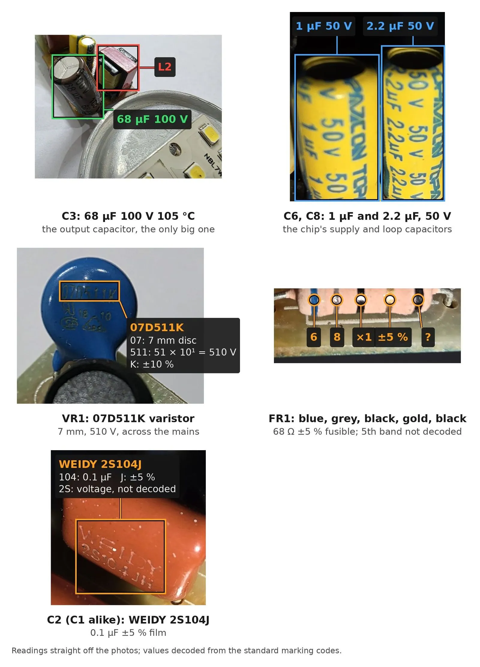
Part markings read off the photos and decoded with the standard codes. One band on the fusible resistor and the voltage code on the film capacitors were never worked out.
The codes also date the bulb, if I’m reading them right. The driver’s board name ends in 180425, which looks like 25 April 2018. The last line on the chip reads week 46, which fits November 2018. The housing says February 2019. So this board revision is dated about ten months before the bulb was built.
The LEDs run hot
The LED board’s silkscreen says NBL7W9S1P2835V1.0, which reads as a 7 W board with
nine 2835 LEDs in series. Working back from the driver, it’s being fed about 8.1 W.
That’s around 16% over the board’s own label, close to 0.9 W per LED.
It’s a lot of heat for a small square of board. About 5.7 W of it has to leave through a smear of thermal grease, into the aluminium cup and out through a plastic housing. Nothing in the circuit watches the LED temperature. copperhead also flags the output capacitor, a 105 °C part sealed in the neck, as the part most likely to limit how long the bulb lasts.
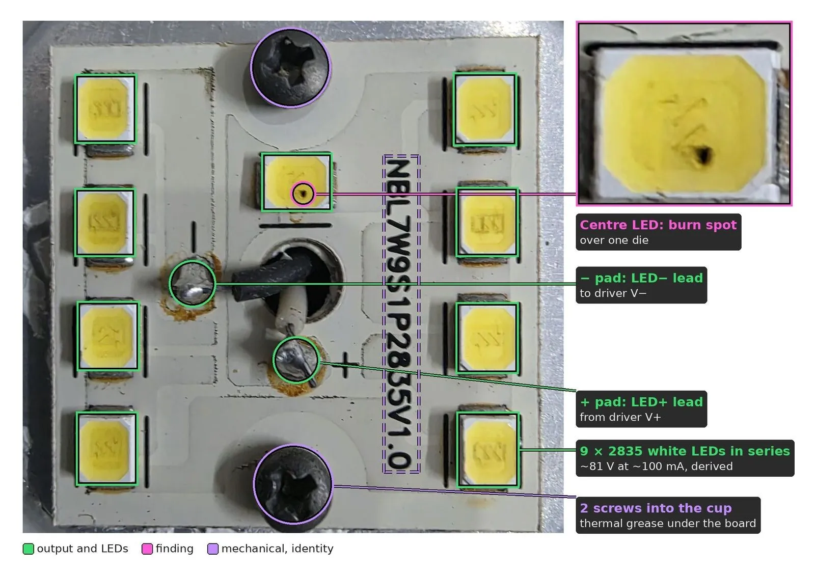
The LED board. The dashed box is the silkscreen that says 7 W, and the inset is the burn on the middle LED. The voltage and current in the labels are worked out from the driver, not measured.
The middle LED has a small black burn mark over one of its dies. I can’t prove that’s what made my bulb dim and flicker because I never powered it again to check. But I found a repair video of another flickering Crompton bulb[1] that shows the same board with the same kind of burn on a different LED.
Pinning down the chip
Working from the circuit around it, the first pass said it was a Bright Power Semiconductor part from the BP2335 family[6]. Then I read the marking by eye. I read it several times and got a different answer almost every time: BP2836, then BP2336 or BP2338, then BP2636. The photos weren’t any better and read BP2835, BP2865 or BP2885 depending on the light.
copperhead took my first read and rebuilt everything around BP2836 until it noticed BP2836 only comes in a through-hole package[7] and this chip is surface mount. Next it settled on BP2336J and marked it verified because the second and third lines of the marking were in the right format.
That was too strong and copperhead pulled it back. The same maker prints that format on several different chips[8][9], so a matching format only identifies the maker.
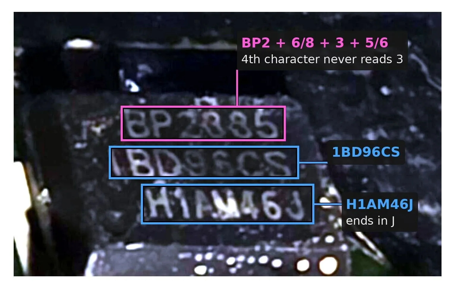
The chip’s marking, brightened. Where BP2336 would print a 3 in the top line, every photo gave a 6 or an 8. My reads by eye gave all three.
The record now calls it BP2336J and the circuit around it backs that up. The evidence alone puts it at 0.55, and I had it commit at 0.75 so the work could keep moving. A couple of beeps from a multimeter on continuity will settle it.
Numbers I don’t like
If an LED fails open, the chip is meant to shut down when the output reaches about 108 V[6]. The capacitor holding that output is rated 100 V. That depends on my reading of three feedback resistors that nobody has traced yet, but if it’s right, a dead LED would push that capacitor 8% past its rating before the chip steps in.
Surge is the other gap. The varistor is rated 510 V, the switch inside the chip is rated 500 V and there’s only 0.2 µF on the rectified mains between them. Photos cannot show whether the varistor catches a spike before the chip does. Crompton’s current 9 W bulbs advertise 4 kV surge protection[10], and this 2019 one prints no surge rating at all.
With no big capacitor on the mains side, copperhead also expects 17 to 25% flicker at 100 Hz, which is too fast to see directly. It rates that figure as a weak estimate.
What copperhead would change
copperhead’s verdict is that the design was built to meet the standards as cheaply as possible, with reliability second. It meets the power factor and efficiency it has to[11][12] on very few parts, and the LEDs run hot against the board’s label. The changes it suggests are small. Use a 160 V output capacitor. Either add a few LEDs or swap the sense resistor for 2.4 Ω, which brings the current down to about 83 mA for roughly 15% less light. Run a proper surge test at 1 and 2.5 kV before touching the varistor.
Each of these findings also becomes a rule copperhead can check on a new design before anyone builds it:
- the output capacitor is rated at least 1.1 times the overvoltage trip
- LED power is checked against the LED’s own rating, never the board’s label
- a driver with no bulk capacitance on the mains side gets a flicker estimate
- every resistor in a high-voltage divider is checked against its working voltage
- the varistor’s clamp voltage is checked against the switch’s breakdown voltage
What I still don’t know
Everything here came from photos, so none of it has been measured yet. The copper is hidden under solid green solder mask, so the 16 connections in the circuit come from the chip’s reference design. Only three of them can be seen in a photo. The LED current depends on the chip identification, and the 8.1 W assumes the driver is 90% efficient. It’s also one bulb from 2019, and Crompton’s newer ones may be built differently. One of the repair videos already shows a Crompton 9 W driver of a different design[3].
The next step is a multimeter. copperhead has already marked about 40 pairs of points to probe across the photos, all with the bulb unplugged. It also wants a sharper photo of the chip. Measuring it with power on is a job for someone with an isolation transformer. Every part of this lamp, the LED board included, sits at mains voltage when it’s switched on.
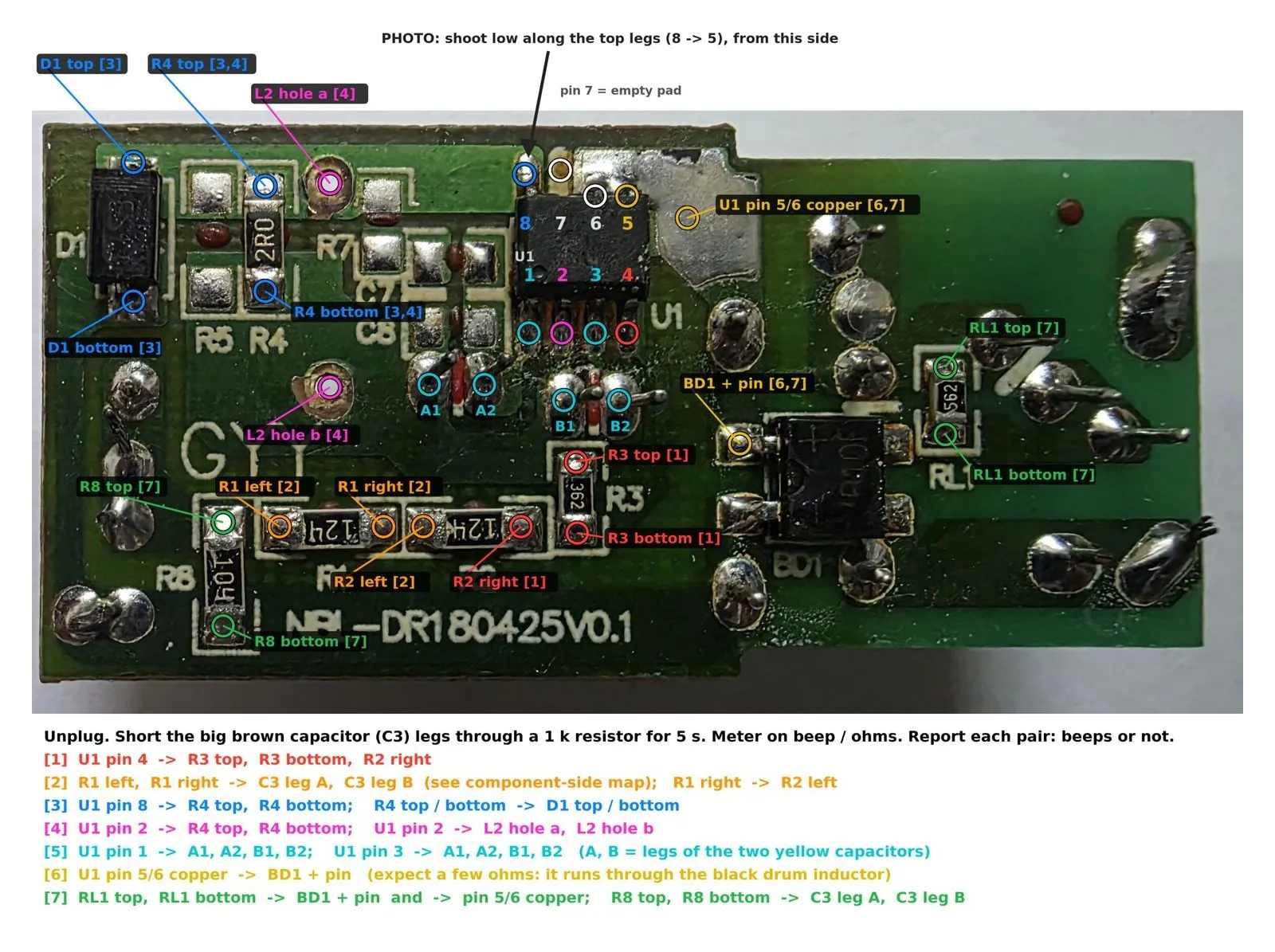
The copper side of the probe map copperhead drew on my own photo, carrying checks 1 to 7. The rest are on the other photos, and checks 1 and 5 decide what the chip is.
The full report
Everything above is in the report[13] with the working shown. The full version runs to 59 pages, and its appendices come straight out of copperhead’s data: the parts list, the connections with a confidence on each, the evidence and all 19 unknowns. The summary[14] is five pages. copperhead wrote the report’s text and drew its figures, and I didn’t edit either. My part was the photos, a few reads of the chip by eye and telling it when to stop guessing and commit.
The full report and the summary. Each opens the PDF.
| Document | Revision | Pages | File |
|---|---|---|---|
| Teardown and reverse engineering report | 1.6.1 | 59 | PDF, 5.8 MB |
| Executive summary | 1.6.1 | 5 | PDF, 1.0 MB |
Both are still marked draft. Nobody has reviewed them yet and they say so on the cover.
References
Each entry says which claim in the text it carries. Web sources were read on 4 and 5 October 2026 and checked again on 12 October 2026.
-
Inside Electronics, IE181: Flickering Crompton LED bulb repair, YouTube.
https://www.youtube.com/watch?v=VkNoUq8p3Is
The other flickering bulb, on the sameNBL7W9S1P2835V1.0LED board as mine with a burn mark over a die on a different LED. Read from the thumbnail and from storyboard frames 160 pixels wide because the video would not download. -
Inside Electronics, IE200: Flickering Crompton 9W LED bulb repairing, YouTube.
https://www.youtube.com/watch?v=0pFO1TV-xJE
A sibling Crompton 9 W lamp made for the government UJALA scheme, with the same housing print layout as mine. Only the first minute could be read at 720p. -
Domestic Technician, two Crompton 9W LED bulb repair videos, YouTube.
https://www.youtube.com/watch?v=_1mgH–IVmI
https://www.youtube.com/watch?v=SUZc-gDzL3I
Other Crompton 9 W drivers with the same mix of parts as mine. The second video shows a driver of a different design altogether. Thumbnails and storyboards only. -
Diodes Incorporated, MB10F bridge rectifier datasheet.
https://www.diodes.com/assets/Datasheets/MB10F.pdf
The bridge’s 1000 V, 0.8 A rating. This is a datasheet for the same part code, not necessarily from the bulb’s own supplier. -
Bourns, MOV-07D series metal oxide varistors datasheet.
https://www.bourns.com/docs/product-datasheets/mov07d.pdf
How07D511Kdecodes: a 7 mm disc with a 510 V varistor voltage. Also a datasheet for the part code rather than for the bulb’s own supplier. -
Bright Power Semiconductor, BP2335J non-isolated buck APFC LED driver, datasheet Rev 1.0.
https://5.imimg.com/data5/IM/TI/NH/SELLER-10637014/bp2335j-bp-semi-non-isolated-buck-apfc-led-driver.pdf
The family the first pass landed on. Its equations stand in for the best-guess chip’s: the 0.200 V sense reference behind the 100 mA figure and the 1.6 V feedback threshold behind the 108 V shutdown. Hosted by a distributor rather than by BPS. -
Bright Power Semiconductor, BP2836D non-isolated buck LED driver, datasheet Rev 1.0, LCSC part C81621.
https://item.szlcsc.com/82773.html
My first read of the marking. It comes in through-hole DIP packages only and has no power factor correction, which is how the board ruled it out. -
Bright Power Semiconductor, BP2336J non-isolated buck active-PFC LED driver, datasheet Rev 2.2, Chinese short form.
https://taoic.oss-cn-hangzhou.aliyuncs.com/8654/product/DDWDZ123_1628647841000.pdf
The best-guess chip: the pin map in the copper-side photo, its 500 V switch and the marking format that turned out to prove nothing. -
Bright Power Semiconductor, BP2636B boost PFC constant-voltage driver, datasheet Rev 1.0.
https://www.bpsemi.com/upload/cn/file/2023-01/col355/1673430594587.pdf
A different chip from the same maker with the same marking format as BP2336J, which is why the format could not identify mine. It is a boost stage, so it could never drive an 81 V string through a 100 V capacitor. -
Crompton, 9 watt LED bulb collection.
https://www.crompton.co.in/collections/9-watt-led-bulb
The 4 kV surge protection claimed for Crompton’s current 9 W bulbs. My 2019 bulb prints no surge rating. -
Bureau of Indian Standards, IS 16102 (Part 2):2012, self-ballasted LED lamps for general lighting services, performance requirements.
https://law.resource.org/pub/in/bis/S05/is.16102.2.2012.pdf
The power factor the bulb has to meet. -
Bureau of Energy Efficiency, Schedule 20, star labelling for LED lamps, 2018.
https://www.beestarlabel.com/Content/Files/LED_schedule.pdf
The efficacy bands behind the three BEE stars on the housing. 855 lumens from 9 W is 95 lumens per watt, inside the three-star band of 90 to 105. -
Teardown and reverse engineering report TD-2026-CRM-001-RPT, revision 1.6.1, 59 pages.
/blog/crompton-led-bulb-teardown-report-rev1.6.1.pdf
Every number in this post with its working, its evidence label and its confidence, plus the appendices copperhead generated from its own data. -
Teardown executive summary TD-2026-CRM-001, revision 1.6.1, 5 pages.
/blog/crompton-led-bulb-teardown-summary-rev1.6.1.pdf
The short version, with the overview photos and the four largest risks.
Independent work, not affiliated with Crompton or Bright Power Semiconductor.